SR-MPLS实验

实验需求:
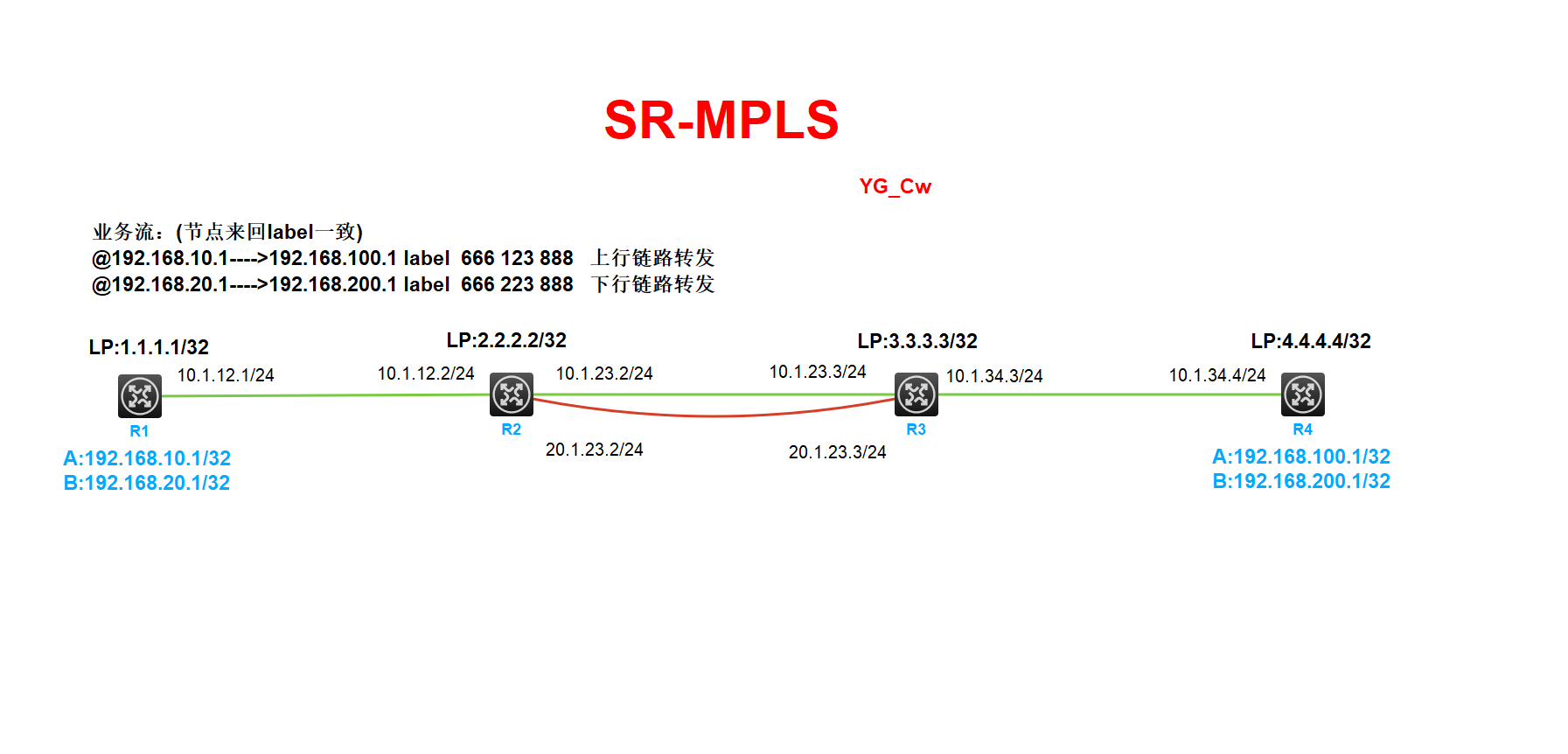
通过部署SR-MPLS实验业务分流
192.168.10.1访问192.168.100.1从R2到R3的上行链路进行转发
192.168.20.1访问192.168.200.1从R2到R3的下行链路进行转发
实验解析
所有设备开始MPLS、MPLS TE功能 ,路由可达 (所有设备均要操作、ospf配置省略)
R1配置:
[R1]mpls lsr-id 1.1.1.1 [R1]mpls te [R1]int g0/0 [R1-GigabitEthernet0/0]mpls enable SR-MPLS配置 [R1]static-sr-mpls adjacency YG_Cw in-label 666 nexthop 10.1.12.2 //配置静态SRLSP的邻接路径信息 [R1]static-sr-mpls lsp lsp1 out-label 666 123 888 //配置静态SRLSP [R1]static-sr-mpls lsp lsp2 out-label 666 223 888 MPLS-TE隧道配置 [R1]interface Tunnel666 mode mpls-te //配置MPLS TE隧道 [R1-Tunnel666] ip address 6.6.6.6 24 [R1-Tunnel666] mpls te signaling static //使用静态SRLSP建立MPLS TE隧道,缺省使用RSVP-TE协议 [R1-Tunnel666] mpls te static-sr-mpls lsp1 //配置隧道使用那个静态SRLSP建立 [R1-Tunnel666] destination 4.4.4.4 [R1]interface Tunnel888 mode mpls-te [R1-Tunnel888] ip address 8.8.8.8 24 [R1-Tunnel888] mpls te signaling static [R1-Tunnel888] mpls te static-sr-mpls lsp2 [R1-Tunnel888] destination 4.4.4.4 将业务交由MPLS-TE隧道转发 [R1]ip route-static 192.168.100.1 32 Tunnel666 [R1]ip route-static 192.168.200.1 32 Tunnel888
R2配置:
[R2]mpls lsr-id 2.2.2.2 [R2]mpls te [R2]int g0/0 [R2-GigabitEthernet0/0]mpls enable [R2]int g0/1 [R2-GigabitEthernet0/1]mpls enable [R2]int S1/0 [R2-Serial1/0]mpls enable [R2]static-sr-mpls adjacency YG_Cw in-label 888 nexthop 10.1.12.1 [R2]static-sr-mpls adjacency YG_Cw1 in-label 123 nexthop 10.1.23.3 [R2]static-sr-mpls adjacency YG_Cw2 in-label 223 nexthop 20.1.23.3
R3配置:
[R3]mpls lsr-id 3.3.3.3 [R3]mpls te [R3]int g0/0 [R3-GigabitEthernet0/0]mpls enable [R3]int g0/1 [R3-GigabitEthernet0/1]mpls enable [R3]int S1/0 [R3-Serial1/0]mpls enable [R3]static-sr-mpls adjacency YG_Cw in-label 888 nexthop 10.1.34.4 [R3]static-sr-mpls adjacency YG_Cw1 in-label 123 nexthop 10.1.23.2 [R3]static-sr-mpls adjacency YG_Cw2 in-label 223 nexthop 20.1.23.2
R4配置:
[R4]mpls lsr-id 4.4.4.4 [R4]mpls te [R4]int g0/0 [R4-GigabitEthernet0/0]mpls enable [R4] static-sr-mpls adjacency YG_Cw in-label 666 nexthop 10.1.34.3 [R4] static-sr-mpls lsp lsp1 out-label 666 123 888 [R4] static-sr-mpls lsp lsp2 out-label 666 223 888 [R4]interface Tunnel666 mode mpls-te [R4-Tunnel666] ip address 6.6.6.7 255.255.255.0 [R4-Tunnel666] mpls te signaling static [R4-Tunnel666] mpls te static-sr-mpls lsp1 [R4-Tunnel666] destination 1.1.1.1 [R4]interface Tunnel888 mode mpls-te [R4-Tunnel888] ip address 8.8.8.9 255.255.255.0 [R4-Tunnel888] mpls te signaling static [R4-Tunnel888] mpls te static-sr-mpls lsp2 [R4-Tunnel888] destination 1.1.1.1 [R4] ip route-static 192.168.10.1 32 Tunnel666 [R4] ip route-static 192.168.20.1 32 Tunnel888
总结:如果将业务发布进ospf则通过ospf进行业务学习将导致所有业务从R2--->R3上行链路进行转发,下行链路无法进行业务转发链路带宽浪费上行链路压力大
[R1]tracert -a 192.168.10.1 192.168.100.1
traceroute to 192.168.100.1 (192.168.100.1) from 192.168.10.1, 30 hops at most, 40 bytes each packet, press CTRL+C to break
 1  10.1.12.2 (10.1.12.2)  1.000 ms  1.000 ms  1.000 ms
 2  10.1.23.3 (10.1.23.3)  1.000 ms  2.000 ms  1.000 ms
 3  10.1.34.4 (10.1.34.4)  1.000 ms  1.000 ms  2.000 ms
[R1]tracert -a 192.168.20.1 192.168.200.1
traceroute to 192.168.200.1 (192.168.200.1) from 192.168.20.1, 30 hops at most, 40 bytes each packet, press CTRL+C to break
 1  10.1.12.2 (10.1.12.2)  1.000 ms  1.000 ms  0.000 ms
 2  10.1.23.3 (10.1.23.3)  1.000 ms  1.000 ms  2.000 ms
 3  10.1.34.4 (10.1.34.4)  1.000 ms  2.000 ms  2.000 ms
故部署SR-MPLS实现分流由R2--->R3上下行链路进行业务分流解决上述问题(注:解决该问题还有其他方案部署SR-MPLS只是其中一种)
[R1]tracert -a 192.168.10.1 192.168.100.1
traceroute to 192.168.100.1 (192.168.100.1) from 192.168.10.1, 30 hops at most, 40 bytes each packet, press CTRL+C to break
 1  10.1.12.2 (10.1.12.2)  2.000 ms  2.000 ms  1.000 ms
 2  10.1.23.3 (10.1.23.3)  1.000 ms  2.000 ms  2.000 ms
 3  10.1.34.4 (10.1.34.4)  1.000 ms  1.000 ms  2.000 ms
[R1]tracert -a 192.168.20.1 192.168.200.1
traceroute to 192.168.200.1 (192.168.200.1) from 192.168.20.1, 30 hops at most, 40 bytes each packet, press CTRL+C to break
 1  10.1.12.2 (10.1.12.2)  1.000 ms  2.000 ms  2.000 ms
 2  20.1.23.3 (20.1.23.3)  1.000 ms  2.000 ms  1.000 ms
 3  10.1.34.4 (10.1.34.4)  3.000 ms  1.000 ms  2.000 ms
抓包查看标签

