PPP CHAP +PPP MP实验
实验拓扑

实验需求
-
按照图示搭建拓扑,并且配置IP地址
-
在RTA配置本地用户以CHAP方式验证对端RTB
-
在RTB配置本地用户以CHAP方式验证对端RTA
-
分别在RTA和RTB上创建MP-group组
-
分别把RTA和RTB的串行接口加入到MP-group组中
-
在PCA或PCB上通过ping命令检查PCB或PCA的互通性
实验解析
1、按照图示搭建拓扑,并且配置IP地址
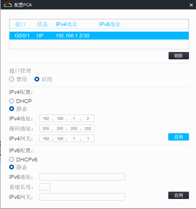
步骤1:在PCA上配置IP地址
步骤2:在RTA上配置IP地址
[RTA]interface GigabitEthernet 0/0
[RTA-GigabitEthernet0/0]ip address 192.168.1.1 30
[RTA]interface Serial 1/0
[RTA-Serial1/0]ip address 10.1.1.1 30
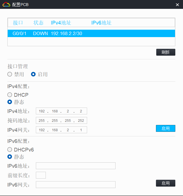
步骤3:在PCB上配置IP地址
[RTB]interface GigabitEthernet 0/0
[RTB-GigabitEthernet0/0]ip address 192.168.2.1 30
[RTB]interface Serial 1/0
[RTB-Serial1/0]ip address 10.1.1.2 30
步骤4:在PCB上配置IP地址
2、在RTA上配置到达192.168.2.0/30网段的路由
[RTA]ip route-static 192.168.2.2 30 10.1.1.2
3、在RTB上配置到达192.168.1.0/30网段的路由
[RTB]ip route-static 192.168.1.1 30 10.1.1.1
4、在RTA配置本地用户以CHAP方式验证对端RTB
步骤1:在RTA上创建本地用户和密码
[RTA]local-user RTB class network
[RTA-luser-network-RTB]service-type ppp
[RTA-luser-network-RTB]password simple pwdpwd
步骤2:配置RTA的串行接口的配置验证方式为CHAP且为验证方,向对方发送用户名 RTA
[RTA]interface Serial 1/0 [RTA-Serial1/0]ppp authentication-mode chap [RTA-Serial1/0]ppp chap password simple pwdpwd [RTA-Serial1/0]ppp chap user RTA [RTA]interface Serial 2/0 [RTA-Serial2/0] ppp authentication-mode chap [RTA-Serial1/0]ppp chap password simple pwdpwd [RTA-Serial1/0]ppp chap user RTA
5、在RTB配置本地用户以CHAP方式验证对端RTA
步骤1:在RTB上创建本地用户和密码
[RTB]local-user RTA class network
[RTB-luser-network-RTA]service-type ppp
[RTB-luser-network-RTA]password simple pwdpwd
步骤2:配置RTB的串行接口的配置验证方式为CHAP且为验证方,向对方发送用户名 RTB
[RTB]interface Serial 1/0 [RTB-Serial1/0]ppp authentication-mode chap [RTB-Serial1/0]ppp chap password simple pwdpwd [RTB-Serial1/0]ppp chap user RTB [RTB]interface Serial 2/0 [RTB-Serial2/0] ppp authentication-mode chap [RTB-Serial1/0]ppp chap password simple pwdpwd [RTB-Serial1/0]ppp chap user RTB
6、分别在RTA和RTB上创建MP-group组
在开始PPP MP实验前,需要将路由器配置恢复到默认状态
步骤1:在RTA上创建MP-group组,并且配置IP地址
[RTA]interface MP-group 1
[RTA-MP-group1]ip address 10.1.1.1 30
步骤2:在RTB上创建MP-group组
[RTB]interface MP-group 1
[RTB-MP-group1]ip address 10.1.1.2 30
7、分别把RTA和RTB的串行接口加入到MP-group组中
步骤1:把RTA的串行接口加入到MP-group组中
[RTA]int range s1/0 s2/0
[RTA-if-range]ppp mp MP-group 1
步骤2:把RTB的串行接口加入到MP-group组中
[RTB]int range s1/0 s2/0
[RTB-if-range]ppp mp MP-group 1
8、在PCA或PCB上通过ping命令检查PCB或PCA的互通性
步骤1:在PCA上ping PCB的IP地址
<H3C>ping 192.168.2.1
Ping 192.168.2.1 (192.168.2.1): 56 data bytes, press CTRL_C to break
56 bytes from 192.168.2.1: icmp_seq=0 ttl=254 time=1.310 ms
56 bytes from 192.168.2.1: icmp_seq=1 ttl=254 time=1.030 ms
56 bytes from 192.168.2.1: icmp_seq=2 ttl=254 time=0.934 ms
56 bytes from 192.168.2.1: icmp_seq=3 ttl=254 time=1.036 ms
56 bytes from 192.168.2.1: icmp_seq=4 ttl=254 time=1.079 ms
步骤2:在PCB上ping PCA的IP地址
<H3C>ping 192.168.1.1
Ping 192.168.1.1 (192.168.1.1): 56 data bytes, press CTRL_C to break
56 bytes from 192.168.1.1: icmp_seq=0 ttl=254 time=1.183 ms
56 bytes from 192.168.1.1: icmp_seq=1 ttl=254 time=1.085 ms
56 bytes from 192.168.1.1: icmp_seq=2 ttl=254 time=1.088 ms
56 bytes from 192.168.1.1: icmp_seq=3 ttl=254 time=1.185 ms
56 bytes from 192.168.1.1: icmp_seq=4 ttl=254 time=1.173 ms